


YOFC WideBand OM5 Bend Insensitive Multimode Fibre
Descriptions:
YOFC MaxBand® WideBand OM5 Bend Insensitive Multimode Fibre is a 50µm laser-optimized multimode fibre designed for short wavelength division multiplexing (SWDM) applications. Unlike legacy OM4 multimode fibre with high bandwidth at 850nm, YOFC MaxBand® OM5 Bend Insensitive Multimode Fibre has high bandwidth in the 850 nm - 950 nm window and maintaining backward compatiblity with legacy OM4 fibre. WideBand OM5 and multi-wavelength transceivers are a viable solution for 100Gb/s and 400Gb/s multi-wavelength systems.
YOFC MaxBand® WideBand OM5 Bend Insensitive Multimode Fibre complies with or exceeds ISO/IEC 11801-4 OM5 specification, IEC 60793-2-10 A1-OM5 specification, and TIA-492AAAF A1-OM5 specification
Features:
lDesigned for multi-wavelength systems
lHigh bandwidth in the wavelength range of 850 nm - 950 nm
lBackward compatible with legacy OM4 fibre
lSuperior geometry uniformity
lLow attenuation
lHigh bandwidth
lLow differential mode delay (DMD)
lVery low macro-bending sensitivity
lSupport single-wavelength and multi-wavelength transmission system from 40 Gb/s to 400 Gb/s
Benefits:
lCoated with YOFC's proprietary dual layer UV curable acrylate
lHigh resistance to micro-bending
lOptimized performance in tight-buffer cable applications
lStable performance over a wide range of environmental conditions
Applications:
lData centers
lData storage networks
lHigh-performance computing centers a
lOffice centers
lLocal area networks (LAN)
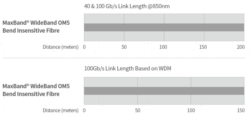
System Link Length:
Specifications:
Characteristics | Conditions | Specified values | Units | |
Geometry Characteristics | ||||
Core Diameter | -- | 50±2.5 | [μm] | |
Core Non-Circularity | -- | ≤5.0 | [%] | |
Cladding Diameter | -- | 125.0±1.0 | [μm] | |
Cladding Non-Circularity | -- | ≤0.6 | [%] | |
Coating Diameter | -- | 245±7 | [μm] | |
Coating/Cladding Concentricity Error | -- | ≤10.0 | [μm] | |
Coating Non-Circularity | -- | ≤6.0 | [%] | |
Core/Cladding Concentricity Error | -- | ≤1.0 | [μm] | |
Delivery Length | -- | up to 8.8 | [km/reel] | |
Optical Characteristics | ||||
Attenuation | 850nm | ≤2.4 | [dB/km] | |
953nm | ≤1.7 | [dB/km] | ||
1300nm | ≤0.6 | [dB/km] | ||
Overfilled Modal Bandwidth | 850nm | ≥3500 | [MHz·km] | |
953nm | ≥1850 | [MHz·km] | ||
1300nm | ≥500 | [MHz·km] | ||
Effective Modal Bandwidth | 850nm | ≥4700 | [MHz·km] | |
953nm | ≥2470 | [MHz·km] | ||
Application support distance on | -- | -- | -- | |
100Gb/s WDM1 | -- | 150 | [m] | |
40Gb/s WDM1 | -- | 440 | [m] | |
40GBASE-SR4 / 100GBASE-SR102 | 850nm | 200 | [m] | |
Numerical Aperture | -- | 0.200±0.015 | -- | |
Group Refractive Index | 850nm | 1.482 | -- | |
1300nm | 1.477 | -- | ||
Zero Dispersion Wavelength(λ0) | -- | [nm] | ||
Zero Dispersion Slope(S0) | -- | ≤4(-103)/(840(λ0/840)4) | [ps/(nm2·km)] | |
Macrobending Loss3 | -- | @850nm | @1300nm | -- |
2 Turns @ 15 mm Radius | -- | ≤0.1 | ≤0.3 | [dB] |
2 Turns @ 7.5 mm Radius | -- | ≤0.2 | ≤0.5 | [dB] |
Backscatter Characteristics | 850nm & 1300nm | |||
Step(Mean of Bidirectional Measurement) | -- | ≤0.10 | [dB] | |
Irregularities Over Fibre Length and Point Discontinuity | -- | ≤0.10 | [dB] | |
Attenuation Uniformity | -- | ≤0.08 | [dB/km] | |
Environmental Characteristics | 850nm & 1300nm | |||
Temperature Cycling | at -60℃ to 85℃ | ≤0.10 | [dB/km] | |
Temperature-Humidity Cycling | at -10℃ to 85℃ and 4% to 98% RH | ≤0.10 | [dB/km] | |
Water Immersion | at 23℃ for 30 days | ≤0.10 | [dB/km] | |
Dry Heat | at 85℃ for 30 days | ≤0.10 | [dB/km] | |
Damp Heat | at 85℃ and 85% RH for 30 days | ≤0.10 | [dB/km] | |
Mechanical Specification | ||||
Proof Test | -- | ≥9.0 | [N] | |
-- | ≥1.0 | [%] | ||
-- | ≥100 | [kpsi] | ||
Coating Strip Force | typical average force | 1.5 | [N] | |
peak force | ≥1.3, ≤8.9 | [N] | ||
Dynamic Stress Corrosion Susceptibility Parameter(nd, typical) | -- | 20 | -- | |
Remarks: 1. Support distance with SWDM transceivers http://www.swdm.org/msa/
2. Support distances considering maximum cable attenuation of 3.0 dB/km at 850 nm,
maximum total splice/connector loss of 1.0 dB and VCSELs maximum RMS spectral width ≤ 0.45 nm.
3. The launochn dcition for the macrobending loss measurement fulfils that described in IEC 61280-4-1.


Contact us
____________
Shanghai Govo Telecom Co., Ltd.
Add: Room 616, North Building, Fortune 108 Square, 1839#Qixin Road,
Minhang District, 201101, Shanghai, China
Email: gw@gwfiber.com; veronica@govochina.cn
Contact: Ms. Veronica Zhao
Office: +86 21-6 0 7 1 2 3 2 5
Mob: +86 1 3 7 8 8 9 1 3 2 6 7
Skype: govochina
Products
_________
Fiber Optic Tool & Tool Kit
Fiber Optic Splicing Equipment
Fiber Optic Test Instrument
Ethernet Cable Tester
Fiber Optic Cable
Optical Fiber
